This is the Drexel Engineering 103 blog for group 068-06. The goal of this lab is to create a LED fixture that can be implemented into a dementia ward at St. Francis Country House to help the health of the patients there. We are working with Group 068-05 to achieve this goal of creating a working prototype. Our group is primarily focusing on the manufacturing of the physical light fixture while the other group is working on programming the LEDs to simulate daylight.

Monday, June 3, 2013

Completed LED Luminaire

In coordination with Group 5, we have successfully completed the LED luminaire.


This is a picture of the bottom portion of the light fixture with the heat-sink attached and the ambient light LEDs attached.


This is a picture of the luminaire with a make-shift top portion (made of foam-board) to show the reflection of the LEDs off the top portion of the light fixture.


This is a photo of the luminaire on and reflecting off of the foam-board model.


Saturday, June 1, 2013

Heatsink with LEDs

We are one step closer to the completed product: We have the finished heatsink complete with the harsh, white LEDs!


The harsh, white, LEDs are located on the middle and sides of each star, with a total of 20 LED strips on the heatsink. The heatsink with LEDs will be located in the middle, bottom portion of the light fixture.


Heatsink Construction

The purpose of the heatsink is to distribute the heat of the harsh, white LEDs located in the center of the light fixture. The fixture, shown below, is composed of a 4-inch threaded bolt, several metal "stars" that will hold the LEDs, and nuts that will lock the "stars" in place:


Final Construction of Fixture

After many hours of work and some trial and error, this is the completed fixture (without LEDs and heatsink):


(top view)


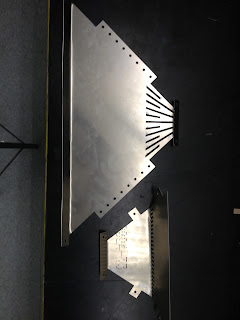
Unfortunately, due to the limitations of the bending tool, our group was not able to complete the top of the light fixture. Instead of making a four sided top-portion, the angles we bent the tabs to resulted in a triangle fixture:


As you can see, we ended up having an extra piece left over. Although we were not able to complete the top of the light fixture, it will not have a huge negative impact on the project as a whole: the top portion of the fixture is for mounting purposes and reflection of the LEDs.


Tuesday, May 14, 2013

Bending and Alteration #2

We are currently in the process of bending each of the pieces! Below is a picture of an large upper piece bent at the top and bottom, and a small lower piece bent at the top tab and at the grid-line


After bending the small piece at the grid-line, an alteration had to be made. In the original design plans, this bend should be a 45 degree bend from the inside. When we attempted to bend it this far, the grid started cracking (most likely due to the amount of holes in the grid and the thinness of the sheet metal). To compensate, we bent it to a 60 degree angle from the inside, as far as it would bend without snapping. Although the fixture may look different than the original design, it should have no effect on the light emission of the LEDs. Below is a picture of the 60 degree angle (measured counter-clockwise)


Monday, May 13, 2013

The Beginning of Prototype Construction and Alteration #1

On Friday, 5/10/13, we started working on building the prototype at the Hess Machine Shop.

First, we sanded all of the sides of the sheet metal pieces to avoid cutting ourselves. Below is a picture of Group Member Chris Fedor sanding down a metal piece:


Although we attempted to bend the metal pieces, we ran into angle issues with the tabs. Due to the limitations of the bending tool at the shop, we will have to bolt the tabs together on the outside of the fixture, as opposed to the inside of the fixture as initially planned. Although the lighting fixture will look different from the original plans, the outside tabs will not affect the results of the LEDs.

Visiting Computer Components Corporation

On Thursday, 5/9/13, Professor Eugenia Ellis and Chloe Dye went to Computer Components Corporation (CCC), located in North Philadelphia. We met with Frank Cettina and cut the two sheets of aluminum metal into the pieces needed for the light fixture.

To do this, a large laser cutter, shown below, was used. The laser was 1/13,000 of an inch thick and used shop air as an assist gas to blow away the shards of metal left over after being cut (originally, they used Nitrogen gas, but it did not work as well).


In order to clamp down the sheet metal, the original AutoCAD file had to be rearranged. The file was then uploaded into a computer, shown below, which programmed the machine to cut.


Here is a video of the machine working!


And here is a picture of one of the components of the heatsink after being cut!


Tuesday, May 7, 2013

Project Organization

To more easily view the images below, click on them to bring the images to full screen. 


In the above Gantt Chart, the colored blocks indicate the scheduled (estimated) time, and the black bars in the colored blocks indicate the completion of each task.
The program used for this is Open Project or OpenProj. It can be found here: http://sourceforge.net/projects/openproj/

Monday, May 6, 2013

DIALux Simulation

DIALux is a very powerful piece of software that allows for its users to simulate how bright a room with be depending on what light fixtures and windows are installed.  It is very useful in designing buildings and houses because it can predict how bright the room will be and then the designer can adjust the fixtures to suite the room's needs.

For this project, we modeled a few of the rooms at St. Francis Country House where our prototype light fixture would be installed.  Unfortunately, we could not model the actually prototype fixture because there are certain features about our fixture that we don't know, such as its light distribution, that can only be obtained from prototyping and testing.  So instead, we took a generic 2' by 2' fixture and adjusted its luminosity and its power.  We also adjusted the fixture so that it would be at the same height as the prototype that we are currently building.  The results are shown below.

Figure 1: DIALux Rendering of St. Francis Country House with lights at 100%

Figure 2: DIALux False Color Rendering of St. Francis Country House with lights at 100%

Figure 3: DIALux Rendering of St. Francis Country House with lights at 50%

Figure 4: DIALux False Color Rendering of St. Francis Country House with lights at 50%

Figure 5: DIALux Rendering of St. Francis Country House with lights at 25%

Figure 6: DIALux False Color Rendering of St. Francis Country House with lights at 25%


For this rendering, it was assumed that the light from other rooms was non-existent and that all the windows and doors were closed.  We decided to do the simulation this way because we felt like it is almost a worse case scenario because here the illumination is coming from only the prototype fixture.  The values of the isolines on the floor are a measure of how bright the room is as a values of foot candles.  With the fixtures at full brightness, DIALux showed a value of close to 75 foot candles across the entire floor which is actually quite bright.  It is actually almost too bright, especially for a dementia ward, which means that the fixtures won't need to run at full brightness which will make then even more energy efficient.  We also ran simulations at 50% and 25% which produced values of  37 foot candles and 20 foot candles respectively.  

Center Heat Sink Design Plan


This image shows the design plan for the center heat sink for our prototype.  There will be about twenty of these stacked on top of each other with washers in-between.  This will allow for greater airflow to the LEDs which will allow them to stay cooler and last longer.  The hole in the center will allow for wring to pass through to the LEDs and keep the overall look of the fixture cleaner.  The LEDs will be four strips of LEDs mounted to the center of the light and they will attach to the inner square.

Cutting the Sheet Metal

Unfortunately, due to scheduling conflicts and dimensional problems with our sheet metal and the shop tools at the Hess Shop, our team was not able to cut the sheet metal on time. In order to cut our sheet metal, we contacted the Computer Components Corporation, located in Philadelphia. The person in charge of the CNC machine, Frank Cettina, has approved of our CAD drawings and agreed to let us use the CNC machine this Thursday, 5/9/13, at no cost!

Additionally, this is the file that we'll be cutting off of.

Monday, April 29, 2013

Fixture: Altered Design and Cutout

These are the new pieces designed for the fixture. There will be four of each type. Each piece is tabbed to make combining the pieces easier.
The pieces combine at the midpoint as shown. The lower pieces is less wide than the upper piece at the midpoint, because the lower components will fit into the upper components.
The pieces will be cut from two 1/8" thick sheets of aluminum metal. It is 24" x 48". Two of the upper components and four of the lower components fit onto one sheet. There is spare metal from the second sheet which will only have two upper components cut out of it. This metal will be kept as a safety measure in case problems arise in cutting or bending the sheet metal.

Thursday, April 18, 2013

Week 1-3 Group Meeting Reports

Group Meeting #3
Date of event: Wednesday, 4/10/2013. 5pm

Out of Lab Group Meeting:

Meeting Objectives:

  • Order the necessary amount of sheet metal to start work on the prototype
  • Start working with DiaLux to simulate how the prototype will work upon completion
--------------------------
  • Wanted to double-check with Mark Shiber that we were ordering the correct sheet metal before actually placing the order
  • Started creating a CAD model of the light fixture
  • Started creating a simulation in DiaLux of the fixture
--------------------------
Thoughts:
  • What are the exact dimensions of the room in St. Francis Country House where these fixtures will be installed?
  • Is there any way to create a custom light fixture in DiaLux?
  • How exactly does the fixture mount in the ceiling?

*Originally posted by Chris Fedor on 4/10/2013 at 8:12 PM


In-Lab Meeting #1

Date of event: Tuesday, 4/9/2013. 3-5pm

In-Lab Group Meeting

Meeting Objectives:

  • Talk to Prof. Ellis about some of the questions we had
  • Meet with Group 5 to see how their progress is coming along on the project
  • Meet Mark Shiber in the machine shop and discuss a plan on building the prototype
--------------------------
  • Met with Mark Shiber who told us where to order the necessary material from
  • With the help of Mark Shiber, we were able to develop a plan on how to build the fixture
  • Presented our Project Proposal to Prof. Ellis and the rest of the class
  • Defined the major objectives of the week as modeling the fixture in CAD and in DiaLux and ordering the material to start with the assembly of the prototype
--------------------------
Thoughts:
  • How long is it going to take to build and assemble the fixture in the machine shop?
  • When does Group 5 want the completed prototype by so they can start adding their components to the prototype?