There
are two chemicals in the human body that make humans wake up and
go to sleep every day: serotonin and melatonin. Serotonin, which
is released when the body absorbs daylight, is responsible for
waking the body up, regulating appetite and sleep, and helping
memory. Melatonin, which is released when the human body absorbs
light from the sunset, is responsible for calming the body and
preparing it for rest. The goal of the Freshman Design Project of
Group 6, which this report will describe from beginning to end,
was to develop a daylight-matching LED luminaire that will
simulate 100% daylight during the day and gradually turn to red
light at night. This “auto-tuning” of daylight will allow the
proper release of serotonin and melatonin in humans. This light
fixture will then be installed in the dementia ward of the St.
Francis Country House to help patients with memory loss,
inadequate sleep cycles, and overall quality of life in a
non-medicinal way. To achieve this goal, two groups will develop
two aspects of the project: programming the LEDs and constructing
the light fixture. Group 6, the contributors of this report, were
responsible for simulating the results of the light fixture in the
room of the St. Francis Country House in the DiaLux program,
modifying the designs provided by Professor Ellis, and building a
physical prototype to attach the programmed LEDs to. After
completing the project objectives, the group successfully
simulated the results of the light fixture in the DiaLux program
and built a fully-functioning model with several structural
alterations to be addressed in future work.
Contents
1 Introduction. 3
1.1 Problem Overview.. 3
1.2 Existing Solutions. 3
1.3 Project Objectives. 3
2 Technical activities. 4
2.1 Project Timeline. 4
2.2 Project Budget 4
2.3 DiaLux Simulation. 5
2.4 AutoCAD Design. 6
2.4 Prototype Construction. 8
3 Results. 9
3.1 DiaLux Simulation Results. 10
3.2 Prototype Results. 11
4 Future Work. 13
5 References. 14
Figure 1: Design plan for LED luminaire. 2
Figure 2: 3D Model of lighting fixture. 2
Figure 3: Completed prototype. 2
Figure 4: Part of the floor plan for St. Francis Country House. 5
Figure 5: Initial cutout design. 6
Figure 6: Upper and lower pieces, holed. 7
Figure 7: Heat-sink. 7
Figure 8: Aluminum sheet cut-out template. 8
Figure 9: Laser cutter computer 8
Figure 10: .dxf file re-arrangement of AutoCAD files on two sheets of metal 8
Figure 11: Laser cutter at CCC.. 8
Figure 12: Group Member Chris Fedor sanding. 9
Figure 13: Group Member Chloe Dye bending. 9
Figure 14: Heat-sink (without LEDs) 9
Figure 15: Completed light fixture after sanding and bending (without heat-sink or LEDs) 9
Figure 16: Completed heat-sink with LEDs. 10
Figure 17: Completed light fixture with heat-sink and LEDs. 10
Figure 19: DiaLux false color render of St. Francis Country House with lights at 100%.. 10
Figure 18: DiaLux Isolines Rendering of the room at St. Francis Country House with lights at 100%.. 10
Figure 20: 60 Degree bend alteration to lower piece. 11
Figure 21: Incorrectly bent top portion of the light fixture. 12
Figure 22: Foam-board model of top portion of light fixture. 12
Figure 24: Completed LED luminaire with auto-tuning on. 13
Figure 23: Completed LED luminaire with auto-tuning off 13
1 Introduction
1.1 Problem Overview
In
recent studies, it has been proven that different waves of light
affect the human body differently [1].
According to recent
studies, when humans absorb blue light, resulting from the sun
reflecting its rays against the blue sky at its highest point, their
brains release serotonin. This hormone is responsible for the
regulation of mood, sleep, appetite, memory, and learning [1]. When
humans absorb red light, which radiates off of the sun at dawn and
dusk, the human brain releases the hormone melatonin. This hormone
does the opposite of serotonin: it helps control sleep and wake
cycles and calms the body down. In essence, serotonin and melatonin
are responsible for humans practicing the ritual of waking up and
working during the day and sleeping and resting at night [1].
As
humans grow older, the rate at which they receive light decreases at
about 1% each year [1]. This means that an infant will receive about
100% of light and a person at the age of 90 will only receive 10% of
light, which poses a difficulty in releasing serotonin and melatonin.
The obvious problem with this human condition is that the older
humans get, the less they can regulate their sleep cycles and mood,
resulting in a largely uncomfortable elderly population. This problem
is magnified for elderly patients, especially those with mental
syndromes such as Dementia, who do not have a chance to go outside
and absorb the small amount of light necessary to release serotonin
and melatonin that they can.
1.2 Existing Solutions
The
simplest way for the human body to release serotonin and melatonin is
to absorb the sun's light by going outside and physically receiving
the rays of light. For those with low serotonin and melatonin levels,
the most common forms of serotonin and melatonin medication today are
anti-depressants, sleeping pills, and over the counter supplements.
Because elderly patients may be physically incapable of going outside
to receive the sun's rays, one uncommon solution to help aid low
serotonin and melatonin levels is to bring the sun's rays to the
patients.
1.3 Project Objectives
The
purpose of this Engineering Design project was to implement a light
fixture that will provide the 100% daylight required to release
serotonin and the red light necessary to release melatonin to elderly
patients in the dementia ward of the St. Francis Country House. In
order to complete this project, a team of 6 people was broken into
two groups: Group 5 was responsible for programming light-emitting
diodes (LEDs) to simulate daylight and Group 6, the contributor of
this report, was responsible for constructing the physical lighting
fixture prototype.
This
lighting fixture, located in main area of the ward, will help
patients with physical and mental health. The lighting fixture will
contain a set of LEDs that will be programmed to emit 100% daylight
during the day to help release serotonin in patients, and then
gradually turn into red light to allow patients to sleep and hospital
employees to still be able to work throughout the night. The lighting
fixture will be composed of 2 entities: a rectangular column, called
a heat-sink, and an outer shell that shapes the lighting fixture. The
heat-sink that will extrude from the bottom of the fixture will
contain the LEDs that will be programmed to emit a harsh, bright,
light that will simulate 100% daylight. The outer shell of the
lighting fixture will house more LEDs that will be programmed to emit
a soft, ambient light to offset the harshness of the lights located
on the heat-sink. These LEDs will also help turn the color of the
light from a natural daylight color during the day to a red color at
night.
By
making sure the small percentage of daylight these dementia patients
are able to receive is 100% daylight and red light, the team hopes to
aid these dementia patients with their memory loss, mood, and quality
of life.
2 Technical activities
2.1 Project Timeline
Table
: Estimated project timeline
Task
|
1
|
2
|
3
|
4
|
5
|
6
|
7
|
8
|
9
|
10
|
Literature
and Program Study
|
x
|
x
|
|
|
|
|
|
|
|
|
Lighting
Simulation
|
|
x
|
x
|
x
|
|
|
|
|
|
|
Building
Lighting Fixture
|
|
|
x
|
x
|
x
|
x
|
x
|
|
|
|
Implementing
Electrical Component
|
|
|
|
|
x
|
x
|
x
|
x
|
|
|
Testing
|
|
|
|
|
|
x
|
x
|
x
|
x
|
|
Final
report preparation
|
|
|
|
|
|
|
|
x
|
x
|
x
|
2.2 Project Budget
Table
2: Combined group 5 and 6 daylight-matching LED luminaire budget
Category
|
Projected
Cost
|
Actual
Cost
|
Aluminum
Sheet Metal
|
$40.00
|
$210.00
|
RBG
LED lights
|
$160.00
|
$210.00
|
TOTAL
|
$200.00
|
$420.00
|
2.3 DiaLux Simulation
One
component of Group 6’s final project was a simulation made in the
DiaLux software. The simulation will show how effective the prototype
light fixture will be in the St. Francis Country House. DiaLux was a
very powerful tool which allowed the user to accurately model a space
and then add various light fixtures to measure its illumination
levels in the room. DiaLux provided information on how many lights
needed to be installed in a space in order to provide a desired
illumination, and where lighting fixtures needed to be mounted to
achieve this illumination.
 |
Figure 4: Part of the floor plan for St. Francis Country House
|
The
first step for the DiaLux simulation was to model the specific room
that was being tested. The prototype fixture was designed to
eventually be implemented in the remote dining area shown in Figure
4, but the dining area's surrounding rooms were also modeled to show
how the walls and windows would affect the luminosity of the remote
dining area. The light fixtures were then added to the drawing in
the exact orientation as specified in the drawing. DiaLux did not
allow the user to create a custom light fixture because certain
values, such as lighting curves, needed to be specified. In
replacement of the custom light fixture constructed by Group 6, a
generic two foot by two foot fixture was used to simulate the effects
of the LED luminaire. The wattage and the luminosity were adjusted
for the values that were going to be used on the fixture to ensure
maximum simulation results.
Once
everything was modeled in DiaLux, various calculations were performed
within the software, including how bright the fixture would actually
be in the designated room. For these calculations, it was assumed
that all the windows were closed so natural sunlight would not
interfere with LED luminaire's actual results. It was also assumed
that the doors to the other remote dining area, as well as the
kitchenette, were open to reduce the amount of light reflected off
the walls. With these conditions, it was almost a “worst-case
scenario” for seeing how bright the room would be.
2.4 AutoCAD Design
The
LED luminaire light fixture was based on an aluminum sheet metal
structure. This structure was defined by several parts designed in
AutoCAD 2013. Based on an initial design developed by Dr. Eugenia
Ellis, the structure of the light fixture was intended to be cut and
bent from four copies of a single cut-out, as shown in Figure 5.
 |
| Figure 5: Initial cutout design 6 |
The
design shown in Figure 5 shows the main piece for the fixture design.
The initial drawing included bend-lines, annotations, and LED
representations which had to be removed for the purposes of
construction: the LED representations and annotations obstructed the
view of the design and the laser cutter used to cut the pieces would
have confused the bend lines for cut-lines.
After
taking into consideration these factors, the design was altered to
accommodate several more changes. Since the fixture had to be cut
from two 24”x48”x1/8”aluminum sheets, the single piece in
Figure 5 needed to be broken into two sections. These two separate
sections, as seen in Figure 6, were labeled the “Upper Piece” and
the “Lower Piece”. Both the Upper and Lower Pieces were cut four
times each. When combined, the four upper pieces formed the “Upper
Section” and the four lower pieces combined to form the “Lower
Section”. The upper and lower sections matched up to the original
cut-out design and combined at the center 3”x1” section.
Second,
to simplify combining the pieces, holed tabs were added along the
sides of the cut-outs. These tabs were literally extensions of the
initial cut-outs. Bolts were to be placed in these holes to allow the
components to be more easily combined and welded together. These tabs
can be seen in Figure 6 as well.
 |
| Figure 6: Upper and lower pieces, holed |
 |
| Figure 7: Heat-sink |
Third,
3”x3”, holed “X-pieces” were designed in AutoCAD to combine
into a heat-sink, acting as the mounting piece for the central, white
LEDs. The purpose of the heat-sink is to passively dissipate heat
into the surrounding air to avoid over-heating of the LEDs. The
components of the heat-sink had an “X-like” appearance, as shown
in Figure 7. These "X-pieces" will be mounted by passing a
central bolt along with one nut placed in between each individual
"X-piece". Several strips of LEDs will then be attached on
the sides of the heat-sink to create the desired harsh, white light
effect. Additional LEDs will be placed along the outside of fixture
as previously shown in Figure 4 to create the changing, ambient light
effect. Lastly, all of the pieces will be arranged to fit on the two
24”x48” aluminum sheets. Specifically, four upper sections, four
lower sections, and 22 "X-pieces" which compose the
heat-sink were arranged onto two 24”x48” rectangles, as shown in
Figure 8.
 |
| Figure 8: Aluminum sheet cut-out template |
2.4 Prototype
Construction
After
finishing the AutoCAD design, the group had to cut the pieces of the
lighting fixture out of aluminum sheet metal. Since the metal cutter
at the Hess Laboratory could not accommodate a 24"x48"
sheet of metal, the group used a laser cutter at Computer Components
Corporation that could accommodate the large sheet size. The laser
cutter, as shown in Figure 10, cut at a width of 1/13,000 of an inch
and used shop air as an assist gas to blow away metal shards. The
AutoCAD file shown in Figure 8 had to be rearranged in order to be
clamped to the laser cutter machine, as shown in Figure 9. The
re-arranged file was then converted into a .dxf file and downloaded
into a computer connected to the laser cutter, shown in Figure 11.
The computer then used this file to program the machine to cut the
sheet metal to the design specifications.
 |
| Figure 9: Laser Cutter Computer |
 |
Figure 11: Laser Cutter at CCC
|
After cutting the pieces out, the edges of the metal pieces had to be sanded down, as shown in Figure 12, and bent using a bending tool, as shown in Figure 13.
 |
| Figure 12: Group Member Chris Fedor sanding |
 |
| Figure 13: Group Member Chloe Dye bending |
Following the bending of the metal, the heat-sink of the light fixture, shown in Figure 14, was built with a 4-inch threaded bolt, several nuts, and several X-pieces, or "stars" that were cut out of the sheet metal. It was placed in the middle column of the completed light structure, which was held together with threaded bolts, as shown in Figure 15.
 |
| Figure 14: Heat-sink without LEDs |
 |
| Figure 15: Completed Fixture after sanding |
After the heat-sink and the shell of the light fixture were combined, the completed fixture was assembled. Figure 16 shows the completed heat-sink with LEDs and Figure 17 shows the completed light fixture with alterations and LEDs
 |
| Figure 16: Completed Heat-sink with LEDs |
 |
| Figure 17: Completed Light fixture |
3 Results
3.1 DiaLux Simulation Results
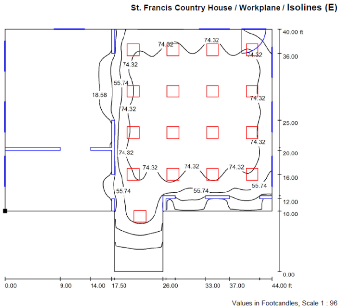
Even though it was impossible to model the exact prototype in DiaLux, the group was able to obtain some very useful data that should be close to how the actual prototype will perform. Both Figures 18 and 19, displayed below, show DiaLux simulations on how bright the room at the St. Francis Country House will be with the lights at 100% of their intensity. Figure 18 shows the luminosity values measured in foot candles of the rooms on the work plane which is three feet off the ground. The simulation showed that the values for most of the room were about 75 foot candles with all of the windows closed and the lights from the other rooms off. This means that the room with the lighting fixture was actually brighter than the average nursing home, which would normally have values between 25 and 50 foot candles [2]. With the lights at 50%, the average luminosity was just shy of 40 foot candles across the entire work plane which was about what it should be in the given environment. Figure 19 shows the false color rendering of the room equipped with the light fixture. It is an illustration of the intensity of the light radiating from the light fixture at any given position in the room.
 |
| Figure 18: DIALux Isoline rendering with the fixtures at 100% |
 |
| Figure 19: DIALux False Color Rendering with the fixtures at 100% |
Through these simulations, the group was able to determine that the prototype will be bright enough for St. Francis Country House. The results showed that the fixture will be so bright that its intensity could be set to about 60% and still be bright enough for the entire room. If it was run at this level, it would mean that the St. Francis Country House would be able to save money on their electric bill compared to the 100% power they are utilizing now. In addition, LEDs are extremely energy efficient, and by not needing to run them at full intensity, the luminaire fixture will prove to be helpful both medically and financially.
3.2 Prototype Results
Although the group followed the design plans as closely as possible, there were some aspects of the finished lighting fixture prototype that differed from the original plan's designs. First, the bolted holed tabs used to hold the sides of the lighting fixture together were not able to be bent on the inside of the fixture: they had to be altered to connect on the outside of the fixture, as shown in the completed fixture in Figure 15. This alteration did not affect the overall result of the LEDs in the fixture.
Another alteration that had to be done to the prototype was the angle of the lower section of the lighting fixture. Due to the properties of the metal, the group was not able to bend the lower section's sides to 45 degrees, facing upward. Instead, they could only be bent to 60 degrees, as shown in Figure 20, to avoid snapping the air-flow slots. This should not make much of a difference in the results of the LEDs because the lighting fixture will be placed in the ceiling and the LEDs will still be able to reflect off of the metal and illuminate through the air-flow slots.
 |
| Figure 20: 120 degree bend alteration to lower piece |
Another major modification that resulted from the prototype construction was the elimination of the top portion of the light fixture, as indicated in the design plans. Due to the limitations of the bending tool, the group was not able to properly bend the tabs of the top portion of the light fixture to the correct angles. This resulted in a 3-sided figure, as shown in Figure 21, instead of 4-sided figure, as indicated in the design plans, and the ultimate failure to attach the top portion of the light fixture to the bottom.
 |
| Figure 21: Incorrectly bent top portion of the light fixture |
Despite not being able to attach the top portion of the light fixture to the bottom portion, it did not have a major negative impact on the overall project: the only purpose of the top portion was to reflect the light of the LEDs and to place the fixture into the ceiling. Since no LEDs were actually placed in the top portion of the light fixture, the bottom portion could still be used to assess the effect of simulated daylight on dementia patients.
For the purposes of this project, a foam-board model of the correct top portion, as shown in Figure 22, was built to show the reflective purpose of the top portion of the fixture, not to actually mount it into the ceiling. The foam-board model was painted white to ensure the total reflection of the ambient-light LEDs that will be reflected off of it. .
 |
| Figure 22: Foam-core model of the top portion of the light fixture |
In conjunction with Group 5 and after simulating results, modifying the original plans, and constructing the light fixture, the following light fixture, shown in Figures 23 and 24, was successfully developed. Even with the alterations, the fixture successfully delivered simulated daylight and gradually turned into red light as the sun went goes down.
 |
| Figure 23: Completed LED luminaire with auto-tuning on |
 |
| Figure 24: Completed LED luminaire with auto-tuning off |
4 Future Work
Following the close of this Freshman Design Project, there are several steps that must be completed before this prototype can become production-ready. First, the alloy of the aluminum metal must be changed. For this project, alloy 2024 was used. In the future, a more bendable alloy such as 5021 should be used for a cleaner bend and for less breaking issues.
In addition, the tabs of the lighting fixture should be removed for future prototyptes. They were not precise and were time-consuming. Instead, the pieces of the fixture should be welded together for a more secure and precise fit. In order to avoid any more bending-tool issues, the .dxf file should be modified to include bending scores. These bending scores, which can be done with the laser cutter, will eliminate any need for the bending tool and will allow builders to bend the necessary angles of the light fixture easily and precisely with only their hands and a protractor.
In addition, the top flanges of the lighting fixture must be modified to fit into the ceiling of the St. Francis Country House. Currently, the prototype must be maneuvered to sit in the ceiling of the Hess Laboratory without mounting. This could cause problems at the St. Francis Country House due to different ceiling types and lack of standard mounting. This mounting issue could be resolved by designing the top of the lighting fixture to be able to mounted into the ceiling using standard tools and screws.
Lastly, the heat-sink should be redesigned to better fit into the light fixture. For the purposes of this project, the heat-sink is held in the middle column of the light fixture with zip ties. Although this is okay to show the effects of the LEDs, it would be hard to maintain at the St. Francis Country Day Home. In the future, the top-most "star" of the heat-sink should be slightly larger than the rest. This would allow the heat-sink to just sit in the bottom portion of the light fixture without being bolted in. This would also result in easy removal for LED replacement and cleaning.
5 References
[1] Laura Beil, " In Eyes, a Clock Calibrated by Wavelengths of Light," The New York Times, pp. D5, 7/11/2011 .
[2] Lighting Design-Footcandle Recomendations, JJI Lighting Group, INC., 5/12/2013.


No comments:
Post a Comment