This is the Drexel Engineering 103 blog for group 068-06. The goal of this lab is to create a LED fixture that can be implemented into a dementia ward at St. Francis Country House to help the health of the patients there. We are working with Group 068-05 to achieve this goal of creating a working prototype. Our group is primarily focusing on the manufacturing of the physical light fixture while the other group is working on programming the LEDs to simulate daylight.

Monday, June 3, 2013

Completed LED Luminaire

In coordination with Group 5, we have successfully completed the LED luminaire.


This is a picture of the bottom portion of the light fixture with the heat-sink attached and the ambient light LEDs attached.


This is a picture of the luminaire with a make-shift top portion (made of foam-board) to show the reflection of the LEDs off the top portion of the light fixture.


This is a photo of the luminaire on and reflecting off of the foam-board model.


Saturday, June 1, 2013

Heatsink with LEDs

We are one step closer to the completed product: We have the finished heatsink complete with the harsh, white LEDs!


The harsh, white, LEDs are located on the middle and sides of each star, with a total of 20 LED strips on the heatsink. The heatsink with LEDs will be located in the middle, bottom portion of the light fixture.


Heatsink Construction

The purpose of the heatsink is to distribute the heat of the harsh, white LEDs located in the center of the light fixture. The fixture, shown below, is composed of a 4-inch threaded bolt, several metal "stars" that will hold the LEDs, and nuts that will lock the "stars" in place:


Final Construction of Fixture

After many hours of work and some trial and error, this is the completed fixture (without LEDs and heatsink):


(top view)


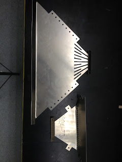
Unfortunately, due to the limitations of the bending tool, our group was not able to complete the top of the light fixture. Instead of making a four sided top-portion, the angles we bent the tabs to resulted in a triangle fixture:


As you can see, we ended up having an extra piece left over. Although we were not able to complete the top of the light fixture, it will not have a huge negative impact on the project as a whole: the top portion of the fixture is for mounting purposes and reflection of the LEDs.


Tuesday, May 14, 2013

Bending and Alteration #2

We are currently in the process of bending each of the pieces! Below is a picture of an large upper piece bent at the top and bottom, and a small lower piece bent at the top tab and at the grid-line


After bending the small piece at the grid-line, an alteration had to be made. In the original design plans, this bend should be a 45 degree bend from the inside. When we attempted to bend it this far, the grid started cracking (most likely due to the amount of holes in the grid and the thinness of the sheet metal). To compensate, we bent it to a 60 degree angle from the inside, as far as it would bend without snapping. Although the fixture may look different than the original design, it should have no effect on the light emission of the LEDs. Below is a picture of the 60 degree angle (measured counter-clockwise)


Monday, May 13, 2013

The Beginning of Prototype Construction and Alteration #1

On Friday, 5/10/13, we started working on building the prototype at the Hess Machine Shop.

First, we sanded all of the sides of the sheet metal pieces to avoid cutting ourselves. Below is a picture of Group Member Chris Fedor sanding down a metal piece:


Although we attempted to bend the metal pieces, we ran into angle issues with the tabs. Due to the limitations of the bending tool at the shop, we will have to bolt the tabs together on the outside of the fixture, as opposed to the inside of the fixture as initially planned. Although the lighting fixture will look different from the original plans, the outside tabs will not affect the results of the LEDs.

Visiting Computer Components Corporation

On Thursday, 5/9/13, Professor Eugenia Ellis and Chloe Dye went to Computer Components Corporation (CCC), located in North Philadelphia. We met with Frank Cettina and cut the two sheets of aluminum metal into the pieces needed for the light fixture.

To do this, a large laser cutter, shown below, was used. The laser was 1/13,000 of an inch thick and used shop air as an assist gas to blow away the shards of metal left over after being cut (originally, they used Nitrogen gas, but it did not work as well).


In order to clamp down the sheet metal, the original AutoCAD file had to be rearranged. The file was then uploaded into a computer, shown below, which programmed the machine to cut.


Here is a video of the machine working!


And here is a picture of one of the components of the heatsink after being cut!